This tutorial illustrates that by using a basepair list, BoulderALE can handle pseduoknots within an alignment. We will also show how a user can get a basepair list and generate a feature list for their alignment. If you have not performed the Overview tutorial, it is recommended, since this tutorial does not cover basic functionality, such as changing filename, saving files, etc. This tutorial is purely theoretical, however; the sequences were based on the mutant RNA pseudoknot structure (PDB: 1KPD).
To begin this tutorial, you should first download and unzip the tutorial files here. Next, you should proceed to the BoulderALE website (http://microbio.me/boulderale).
Note
This dataset is completely theoretical (as you may notice from sequence names), however this tutorial illustrates some functionality, which was not covered in the Overview Tutorial.
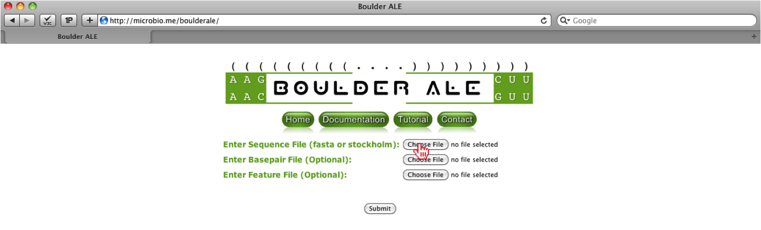
First, you must upload ‘1KPD_pseudoknot.sto’ to the BoulderALE website, by selecting the “Choose File” input button next to ‘Enter Sequence File’.
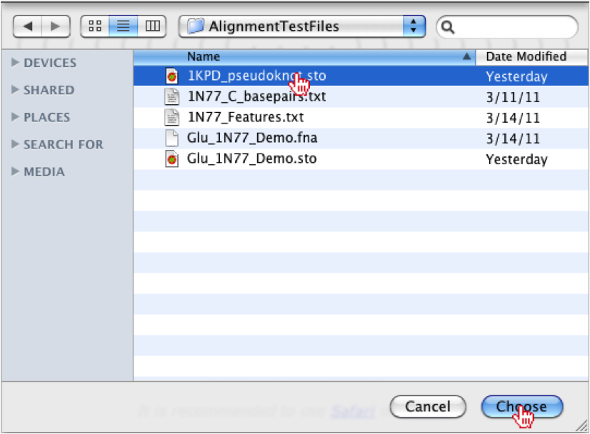
Once the button has been clicked a file menu will appear, where you should select the ‘1KPD_pseudoknot.sto’ file. Once the file is associated, you should click the “Choose” button on the bottom right of the menu.
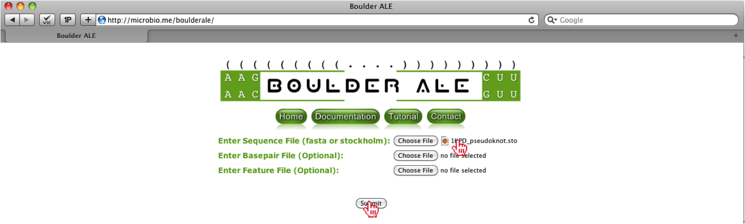
Once the file is chosen, you will see the filename to the right of the “Choose File” button. After selecting the file, you should click on the “Submit” button.
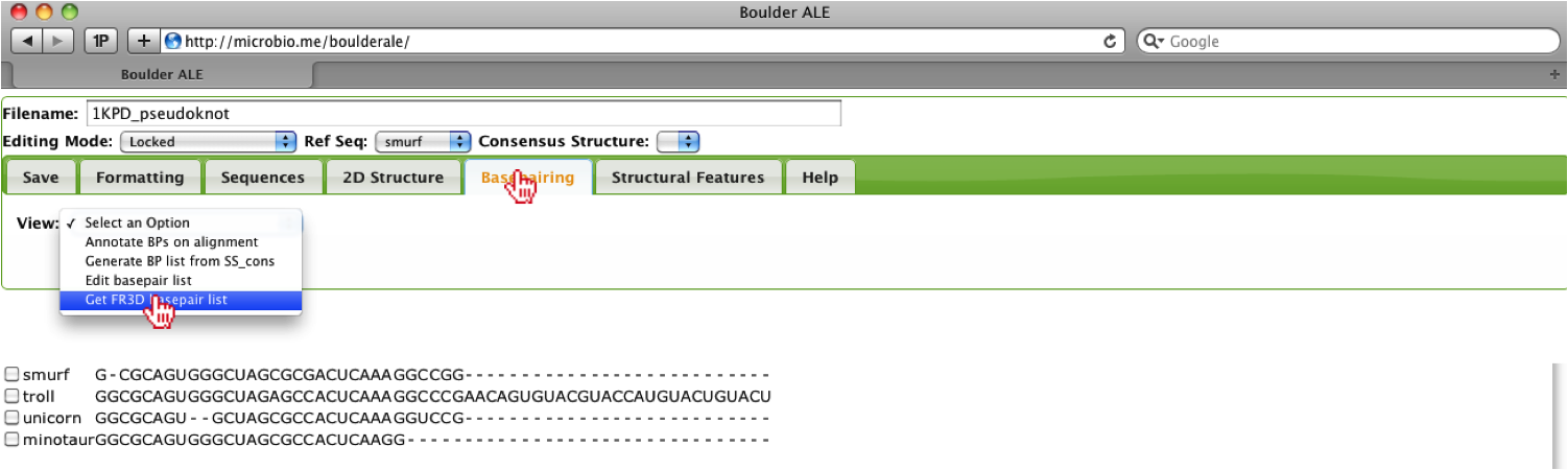
Since the sequences are considered homologous to the mutant RNA pseudoknot structure, we get the sequence for that PDB along with the basepairs list that was generated by the FR3D software tool. To get a basepair list, the user should go to the Basepairing Tab, then select the “Get FR3D basepair list” option.
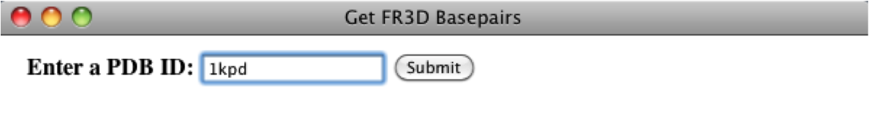
This will open up a console window where the user should enter the PDB ID for the homologous structure, which is “1kpd” for this example. Next, the user should click on the Submit button.
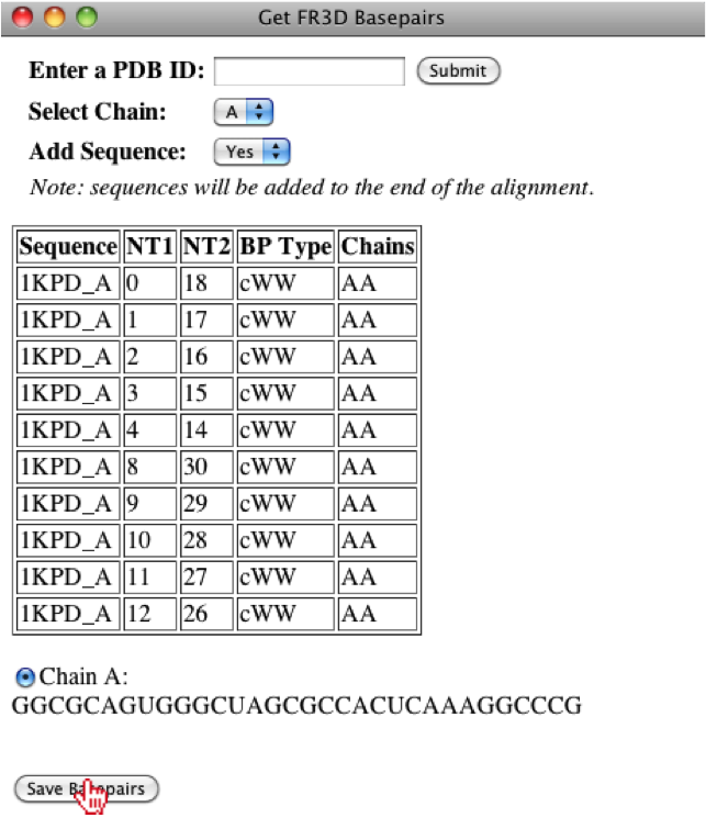
If the PDB is found, then a list of chains will appear and the basepairs associated to each chain will be displayed when selected, however; for this PDB, there is only one chain. The user will also have the option to add the sequence to the alignment and for this case we will append the sequence, since the sequence associated to a basepair list must be in an alignment. For this example, we will leave the default parameters and then the user can save the basepair list.
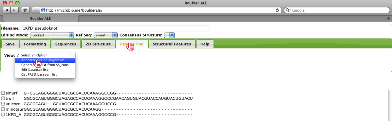
Now that we have associated a basepair list, we can annotate the alignment with the basepairs, by selecting the Annotate BPs on alignment option from the Basepairing Tab.
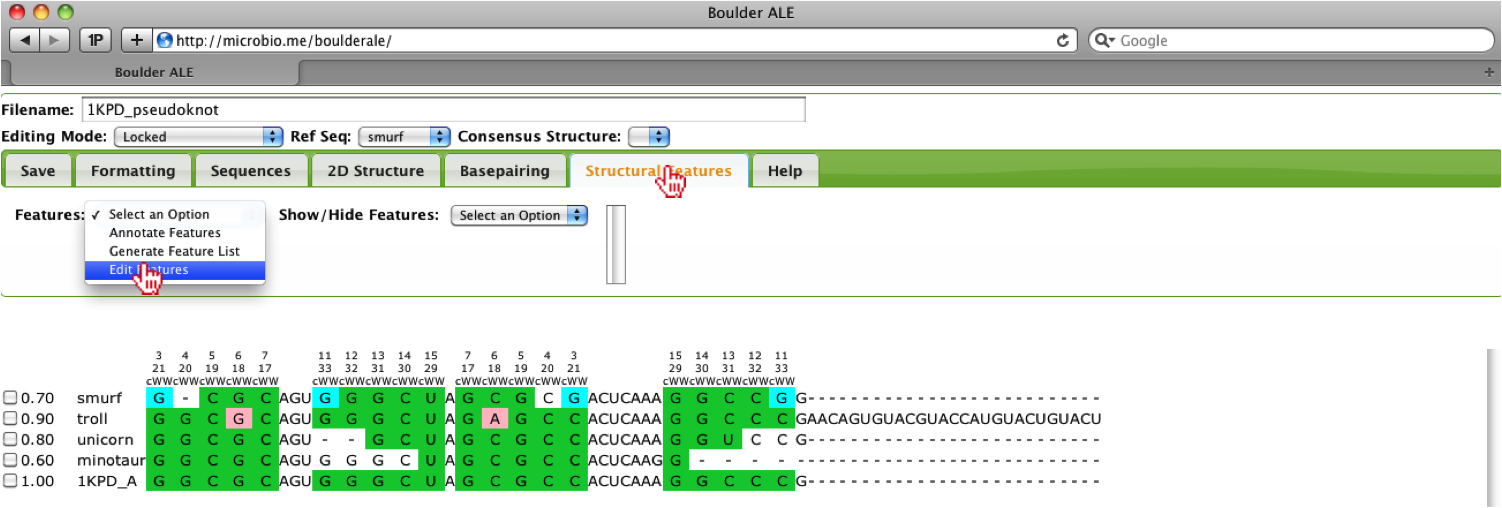
Based on the alignment, you should notice that the troll sequences contains more nucleotides on the 3’ end, so here we will show how a user could hide that region of the alignment. Since no feature list was provided and there is not a dot-bracket to use for generating a generic feature list, we will manually add that region of the alignment as a new feature. To do this, the user should, select the Edit features option under the Structural Features Tab.
This will open up a console window, where the user can add a feature, by clicking on the Add Row button. The user should enter information regarding the feature, for example here we define the Feature Type as a loop, Feature Name as extra_bases, the range as 35-61 (note: these are global alignment) positions and set the color to F0451A.
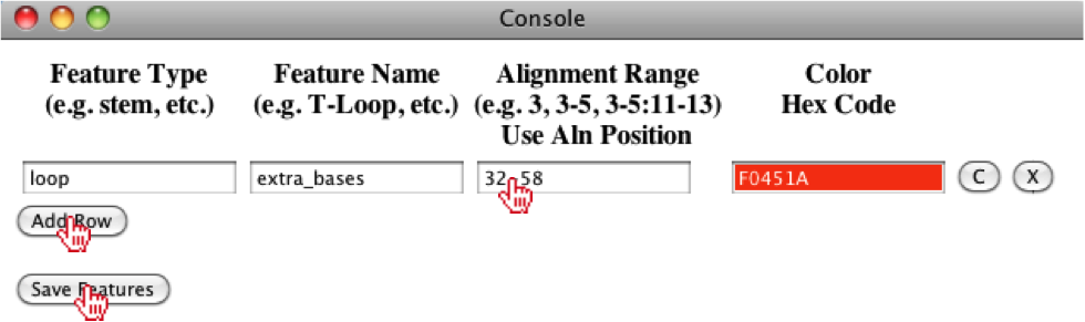
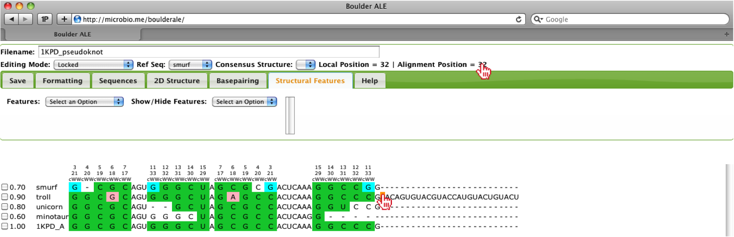
To get the global alignment positions, the user should click on a cell at the beginning of the feature and then a cell at the end of the feature. Upon selecting the cell, the Alignment Position will be displayed above the Tab menu.
Once the user has completed filling out this feature, they can click on the Save Features button, where the feature will be mapped onto the alignment.
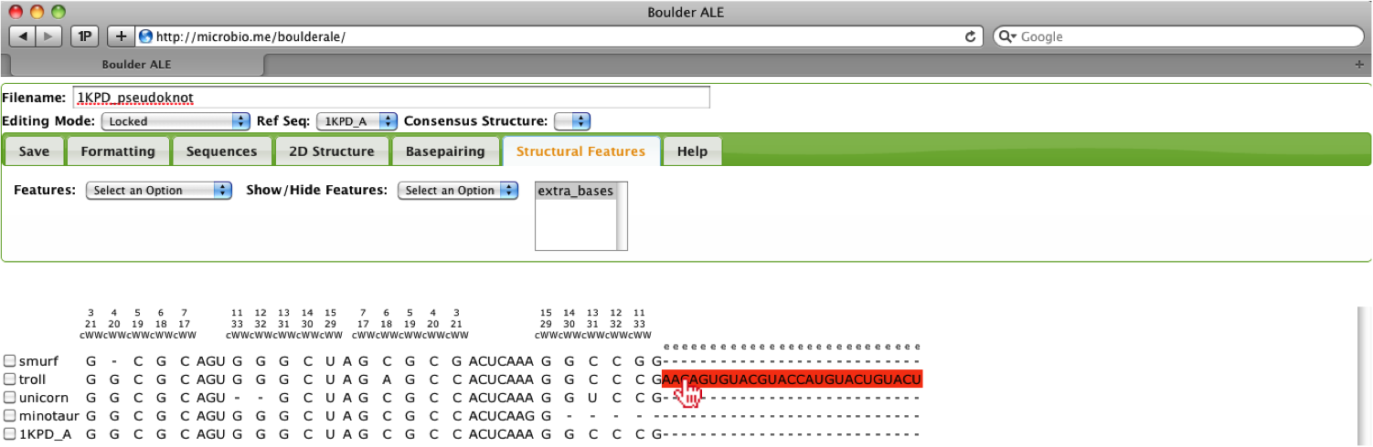
Now that we have added a feature for the extra nucleotides, we can collapse the alignment based on that feature, where the user should select the extra_bases feature from the select-box and select the Hide option under the Structural Features Tab.
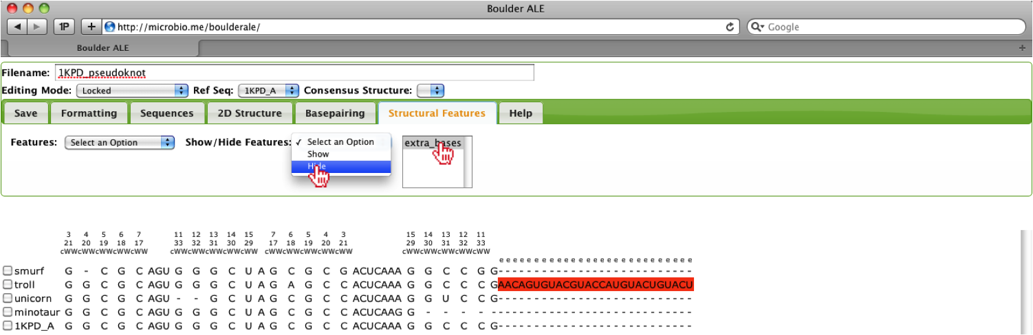
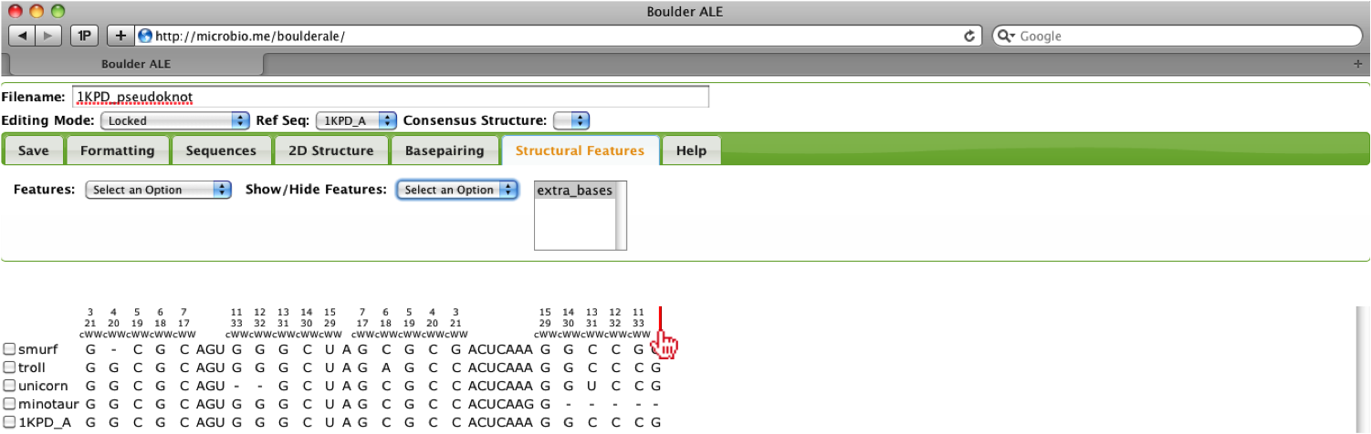
You should now notice that the feature was collapsed and a red line above the alignment denotes the location of the collapse region.
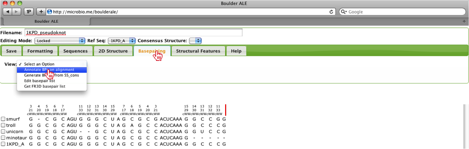
Now that we have collapsed the extra bases, we can re-annotate the basepair colors onto the alignment by selecting Annotate BPs on alignment from the Basepairing Tab. User’s also can edit the alignment while the alignment is collapsed.
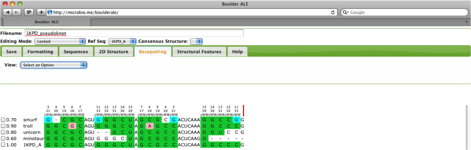
Now the user will notice the alignment has been re-annotated and if they so choose, they can re-show the extra_bases feature from the Structural Features Tab.
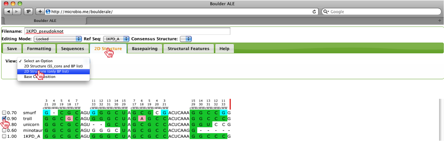
As stated earlier, this alignment is comprised of a pseudoknot, so the standard dot-bracket (consensus secondary structure) annotation scheme is not sufficient, however; we are using a basepair list instead of the dot-bracket annotation, which allows us to evaluate and visualize alignments containing pseudoknots. To visualize the 2D structure, we will select the “troll” sequence and then select the 2D Structure (only BP list) option from the 2D Structure Tab. This alignment does not contain a consensus secondary structure and if it did, the dot-bracket annotation would mess up the visualization, therefore the need to use the BP list only.
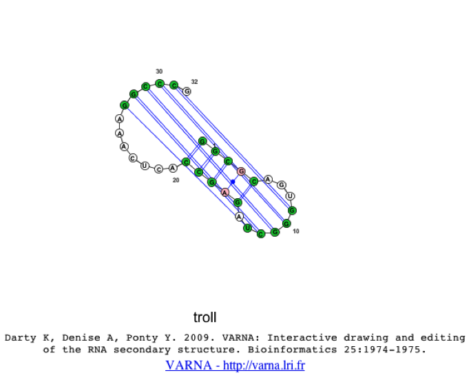
When the 2d structure first appears, you may notice the image appears cluttered.
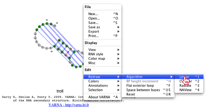
To resolve this, we can redraw the image, using a different algorithm (e.g. linear or circular). To change the algorithm (on a Mac) the user should right-click with their mouse while hovering over the java applet, then they should select Redraw->Algorithm->Linear.
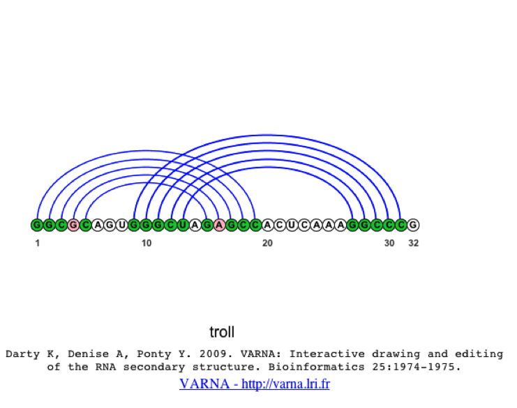
When the image is linear, you should notice the pseudoknot much clearer than in the original structure.
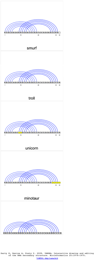
If the user would like to compare the structures of several sequences at once, they can select multiple sequences from the alignment and select the 2D Structure (only BP list) option from the 2D Structure Tab, where a 2D structure will be created for each sequence selected. Again, the user can change the visualization algorithm to linear, so the images are easier to interpret.